A shallow dive into ADCs
In the process of designing a digital synthesiser , I spent the weekend learning a little bit about ADCs. This post provides a basic introduction to what they are, and aims to get you familiar with the high level concepts and terminology used in the ADC domain.
An ADC is an Analog-to-Digital Converter; it translates analog signals into digital inputs which your program can interpret.

Analog signals#
An example of an analog signal you might want to process is the distance you move a thumbstick from its centered position. You can use this signal to determine how to move a cursor on a screen, control where a character is pointing their weapon, and myriad other things.
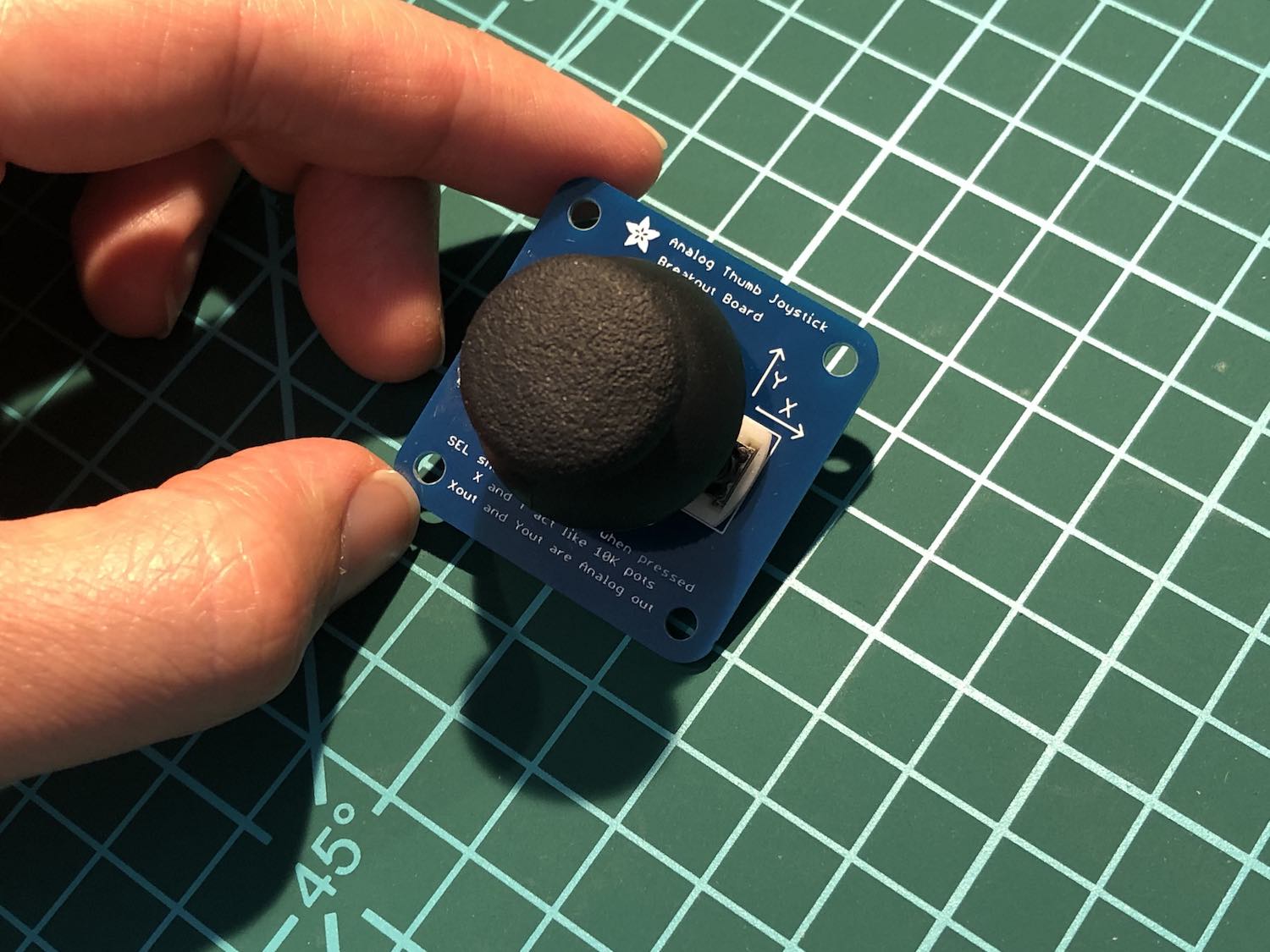
This is a two-axis thumbstick; it senses movement up and down (Y), and left to right (X). You can also press on the stick to trigger a push button (but since that’s a digital output, we won’t focus on it).
Here’s the pinout diagram:
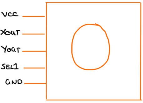
You connect VCC to a power source up to 5 volts and GND to ground. In
return, you get an output voltage from Xout and Yout ranging from 0 to
VCC, proportional to the amount you’ve moved the thumbstick. In its centred
position, you’ll get a voltage of VCC/2 from both outputs.
Analog signals are continuous; that is to say that we can sample the value
of a signal at a given time t and again at t + 1, but there would’ve
been an infinite number of samples we missed in between. Roughly graphed out,
the voltage output from Xout corresponding to the horizontal movement of the
thumbstick might look like this:
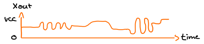
The vertical axis indicates voltage, from 0 volts to the amount supplied to
VCC. The horizontal axis represents time. You can sample the signal at certain
points in time to get an idea of where the user has moved the thumbstick:
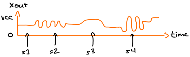
Here we’ve made four samples. At s1, the thumbstick is at its resting position. At s2, the user has moved the thumbstick slightly to the left. s3 shows a large movement to the right, and s4 a large movement to the left.
The number of samples you take in a given period is called the sample rate. The higher the sample rate, the more accurately you’ll be able to map out the change in voltage. Making just four samples above means that we only end up with four discrete values, missing out much of the interesting activity. This phenomena is called aliasing, because your representation of the signal has distorted from reality.
To sample a signal without aliasing, your sample rate needs to be, at a minimum, twice the highest frequency of the signal. This is called the Nyquist rate . Applied to our example, sampling would need to be done at a much tigher interval:
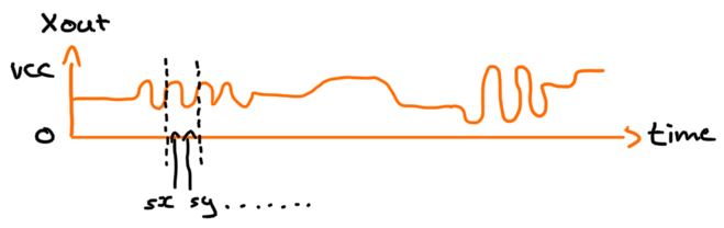
The dotted lines mark the bounds of a cycle in a high-frequency area of the signal. sx and sy show the minimum sample interval we’d need to capture a good representation of this signal.
Above the Nyquist rate, you typically choose a sample rate depending on your application. It’s tempting to sample at the highest rate your equipment will allow, but if you’re responding to thumbstick movement and your display only refreshes at 60Hz, any sampling beyond 60Hz probably won’t make a difference to your user (this practice is referred to as oversampling ).
Now that we’ve explored a little bit about analog signals, it’s time for our shallow dive into ADCs!
Analog to digital conversion#
The job of an ADC is to sample the voltage produced by the analog signal at a given interval, converting it into a digital number that can be understood by your program.
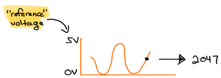
Here, the ADC has taken a voltage reading at about halfway between 0 and 5V (so
let’s call it 2.5V) and has given us the number 2047 as the output. It arrived
at 2047 because of two factors: the reference voltage and the
resolution.
The reference voltage is the upper bound of the measured voltage. It tells the
ADC how to calculate the “level” of the analog signal. The resolution of an ADC
determines how fine of a change in voltage it can recognise, expressed as the
number of bits of the output. The above example assumed a 12-bit ADC which can
output values from 0 to 4095. Since it sampled a voltage halfway up to the
reference, we got 2047 which is roughly 4095/2. If we were using an 8-bit ADC,
we’d get 255/2 or 127.
You should choose an ADC with a suitable resolution for your sensor. A temperature sensor may only provide 255 different output levels, so hooking it up to a 12-bit ADC will just mean additional storage and computation. If your microcontroller has a built-in high resolution ADC, you might be able to configure it in a low-resolution mode as needed.